This time I'm back fulfilling a request by therobomaker957 on how to use lft's chiptune tracker to compose a chiptune and run the tune on an Arduino.
Well, at first, you should grab every piece of code and script from my earlier post. Then, you have to compile the tracker. Assuming you run Ubuntu oder Debian, you'll need build-essential and libsdl for this. Currently, I see no way to rund the tracker in Windows. Perhaps it'll work with cygwin, but it certainly doesn't work with a VirtualBox image of Ubuntu. I tried that before and got no sound out of it.
But before you run the tracker, I think it's time for some overview of creating music using with this concept from the early days of computer music. As the name hints at, you arrange your tune by placing key-ons and key-offs (a bit like MIDI) into several tracks. Within lft's environment, you can have four tracks in parallel, meaning you can play up to four different instruments at the same time - or the same instrument four times, e.g. to play a chord.
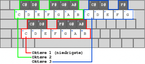
You can put your key-ons (key strokes) into a column of 32 rows, making one track. So if you wanted to play a beat at quarter notes for example, you'd put a note at every fourth line, leaving the rest blank (---). You can use the keyboard to enter different pitches like this (switch octaves with < and >):
This is actually the same as in FastTracker II oder MadTracker, if you've ever worked with these before.
Now, when you run the tracker (don't forget to specify a song file!), you'll see something like this:

On the right, there's the instrument editor (for an explanation of the various commands and key bindings, see lft's tracker readme file in the source zip). In the middle, you can edit the current track (0-128). On the left, you can arrange the different tracks you created into a song. Just enter the number of a track in every of the four different song columns and that track will be played there.
When you're done with editing, save your song - and then export it. The export will create an assembly source file. It contains two song configuration values (length and maxtrack) and a static array of values. However, this array is NOT the one you can paste into the chiptune Arduino sketch. As I couldn't find out how the array in the assembly file and the one in the Arduino sketch were related, I simply had the source file compiled into an object file. Then I dumped the contents of the object file and there it was - the data I needed to paste into the sketch. In the end I wrote a small script (which also uses a simple Java parser) to automate this job of compiling and dumping the assembly stuff.
If you run my script on an exported song (.s file), you should be able to get another file containing the data you can paste into your sketch. All that's left to to then is to adjust the values of MAXTRACK and SONGLEN according to the exported song and you should be the proud owner of your own chiptune playing on your favourite bit of hardware.
Hope this helps (works, even!).